SineTamer® Installation Instructions
ATTENTION – Electrical Installer
Please Read Completely Before Installation to Ensure Optimal Operation of the SineTamer® Suppression Unit
- This SineTamer® Suppression unit incorporates special Frequency Protection Circuitry and the installation of the wire lead length is critical to achieve proper results.
- Insure the Grounding and Bonding of the panel’s neutral and ground wires are up to Electrical Code Standards as well as generator feed wires to the main panel.
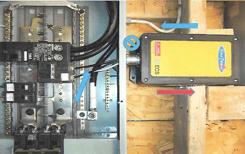
- Units are designed and tested to have lead lengths of wire approximately 6-8 inches in length from the outlet of the suppressor to the tie in point of either the buss bars or a breaker. The shortest possible wire length is critical in the operation of the SineTamer® to achieve the maximum results of the protection circuitry. Try to place the unit in any position possible to ensure all leads are approximately the same length. (20-60 volts/inch can be added to the unit’s let thru voltage above the recommended 6-8 inch lead lengths)
- Lead lengths are to be as short as possible. Do not incorporate severe 90 degree bends in the wiring. The suppressor leads are suggested to be cut to length from factory lengths and fed thru supplied plastic conduit and fittings (if required), into panel and directly into the breaker with no wire loops or sagging wire within the panel. SEE ATTACHED PICTURE FOR LOCATION SELECTIONS.
- The SineTamer® incorporates internal thermal fusing on all modes of protection. This enables the unit to be attached directly to the bus bar if required without a disconnect. We recommend attaching to a breaker whenever possible to avoid shutdowns in case removal is needed.
- The SineTamer suppressor has no load draw other than two small LED signal lights, so breaker size is unimportant. Typically, a 15-amp, double pole breaker is utilized for hook up on single phase applications.
- Please read extra factory installation instructions thoroughly which are included with the unit.
- This SineTamer® Suppression unit incorporates special Frequency Protection Circuitry and the installation of the wire lead length is critical to achieve proper results.
- Insure the Grounding and Bonding of the panel’s neutral and ground wires are up to Electrical Code Standards as well as generator feed wires to the main panel.
- Units are designed and tested to have lead lengths of wire approximately 6-8 inches in length from the outlet of the suppressor to the tie in point of either the buss bars or a breaker. The shortest possible wire length is critical in the operation of the SineTamer® to achieve the maximum results of the protection circuitry. Try to place the unit in any position possible to ensure all leads are approximately the same length. (20-60 volts/inch can be added to the unit’s let thru voltage above the recommended 6-8 inch lead lengths)
- Lead lengths are to be as short as possible. Do not incorporate severe 90 degree bends in the wiring. The suppressor leads are suggested to be cut to length from factory lengths and fed thru supplied plastic conduit and fittings (if required), into panel and directly into the breaker with no wire loops or sagging wire within the panel. SEE ATTACHED PICTURE FOR LOCATION SELECTIONS.
- The SineTamer® incorporates internal thermal fusing on all modes of protection. This enables the unit to be attached directly to the bus bar if required without a disconnect. We recommend attaching to a breaker whenever possible to avoid shutdowns in case removal is needed.
- The SineTamer suppressor has no load draw other than two small LED signal lights, so breaker size is unimportant. Typically, a 15-amp, double pole breaker is utilized for hook up on single phase applications.
- Please read extra factory installation instructions thoroughly which are included with the unit.
Typical TVSS/SPD Locations for Service Entrance, Distribution Panel or Panel Board (no scale)
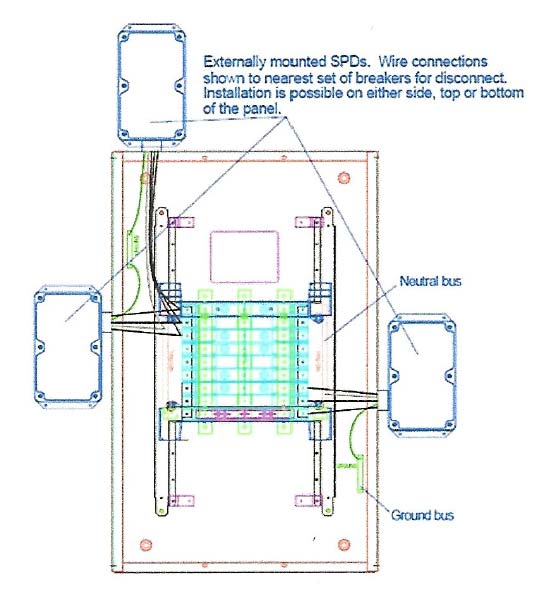
Externally mounted SPDs. Wire connections shown to nearest set of breakers for disconnect. Installation is possible on either side, top or bottom of the panel.
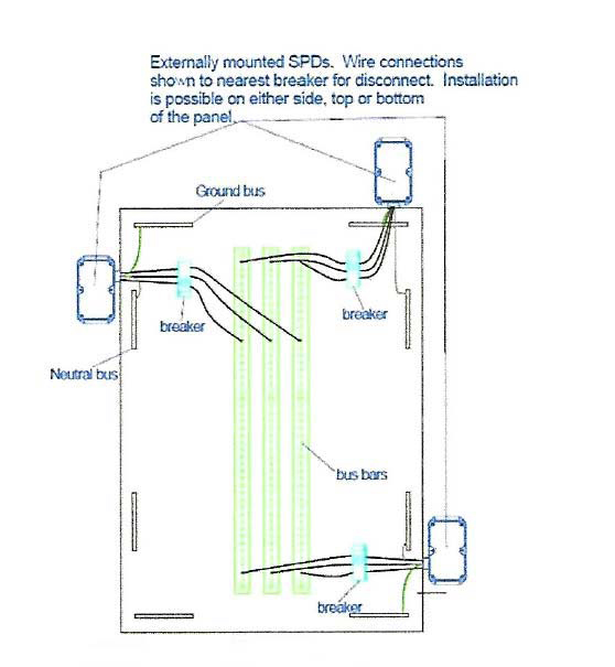
Externally mounted SPDs. Wire connections shown to nearest breaker for disconnect. Installation is possible on either side, top or bottom of the panel.
INCORRECT INSTALLATION
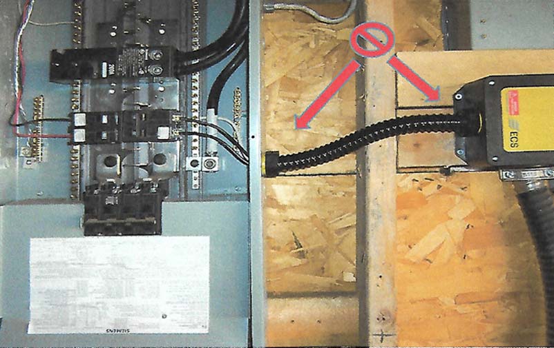
CORRECT INSTALLATION